(Almost) Solderless 3D-printed Handwired Mechanical Keyboard
Written by Sebastian Dümcke on
Tags: 3dprinting keyboards
This title is quite a mouthful. I want to start with a story of how I got here. For most of this project, I am standing on the shoulders of giants. Those interested in the actual build can you skip this the next section.
I ran into mechanical keyboards on social media and thought this was a great combination with 3D printing. My ideas were spurred by a post on geekhack where the author has incorporated hotswap sockets into a 3d printed case. I then thought it must be possible to somehow remove the requirement for hotswap sockets and substitute them for a 3D printed version. However, even after several hours into design I was not able to come up with a good solution for this. Since that time I have been following the Keyboard Builder’s Digest, which in one issues presented the work of stingray127 on Github who designed a fully 3D printer hotswap socket which uses clever folding of the diode and some wire. Having bought my switches a long time ago, I am very happy to finally have completed my first build
Building a Soflev2 split keyboard
I decided to print a split keyboard, because this ensure it can be printed on a small printbed (a full keyboard would not fit). Also I really like the idea of thumb keys and being able to angle the keyboard. To decide which model to build (there are many) I used this nifty comparison app. I printed some of the layouts, positioned my fingers and decided that the column stagger of the Soflev2 looked/felt most comfortable.
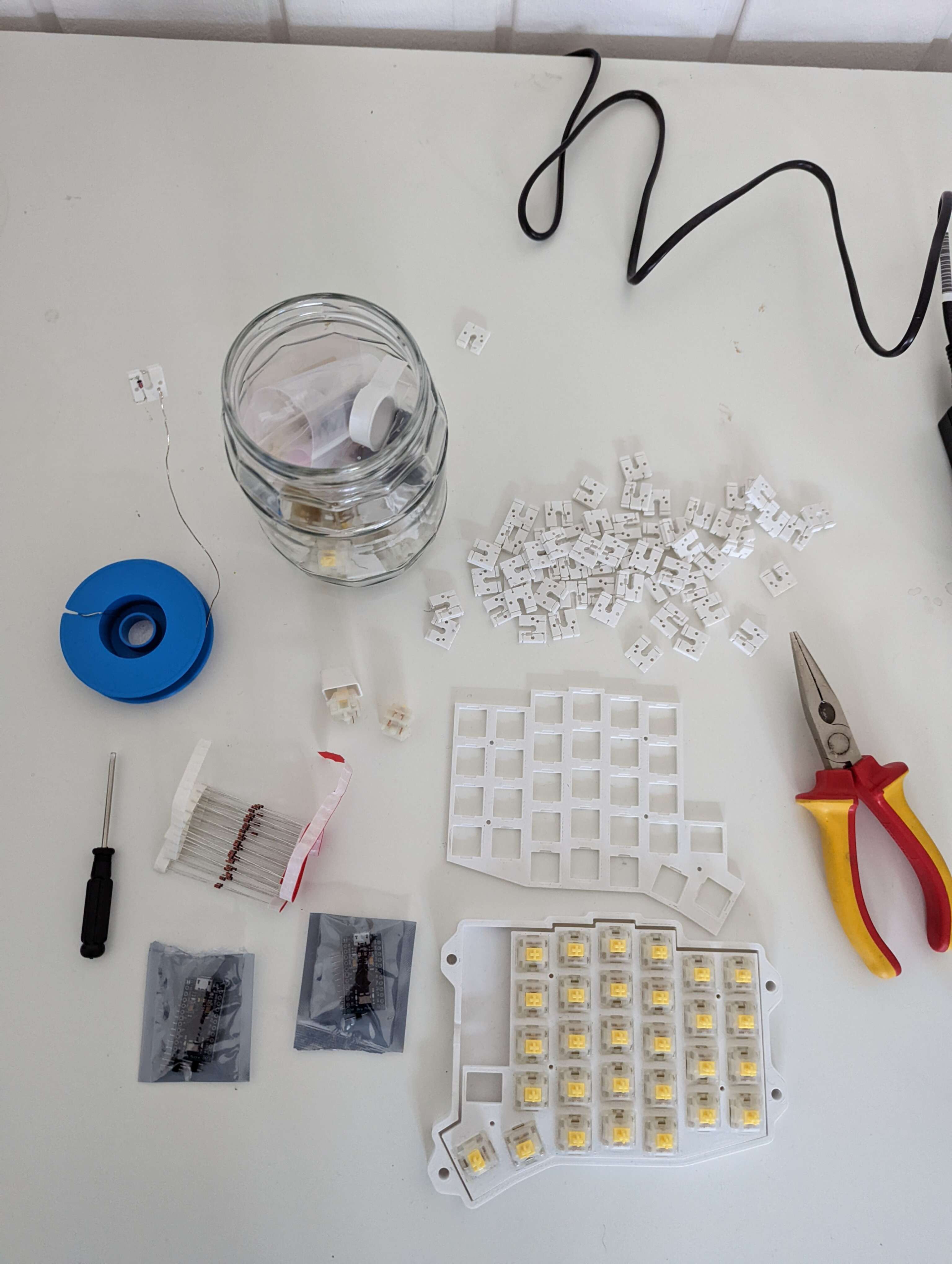
This keyboard uses many printed parts with the exception of:
- 58 1N4148 diodes
- 58 MX style key switches
- 1 EC-11 rotary encoder
- 2 Arduino Pro micro controller
- Dupont female crimps, sockets and crimping pliers
- 0.5mm silver wire
and a lot of patience.
Prepare the sockets
Print 58 hotswap sockets. I used a 0.3mm nozzle and 0.2mm layer height for printing the sockets.
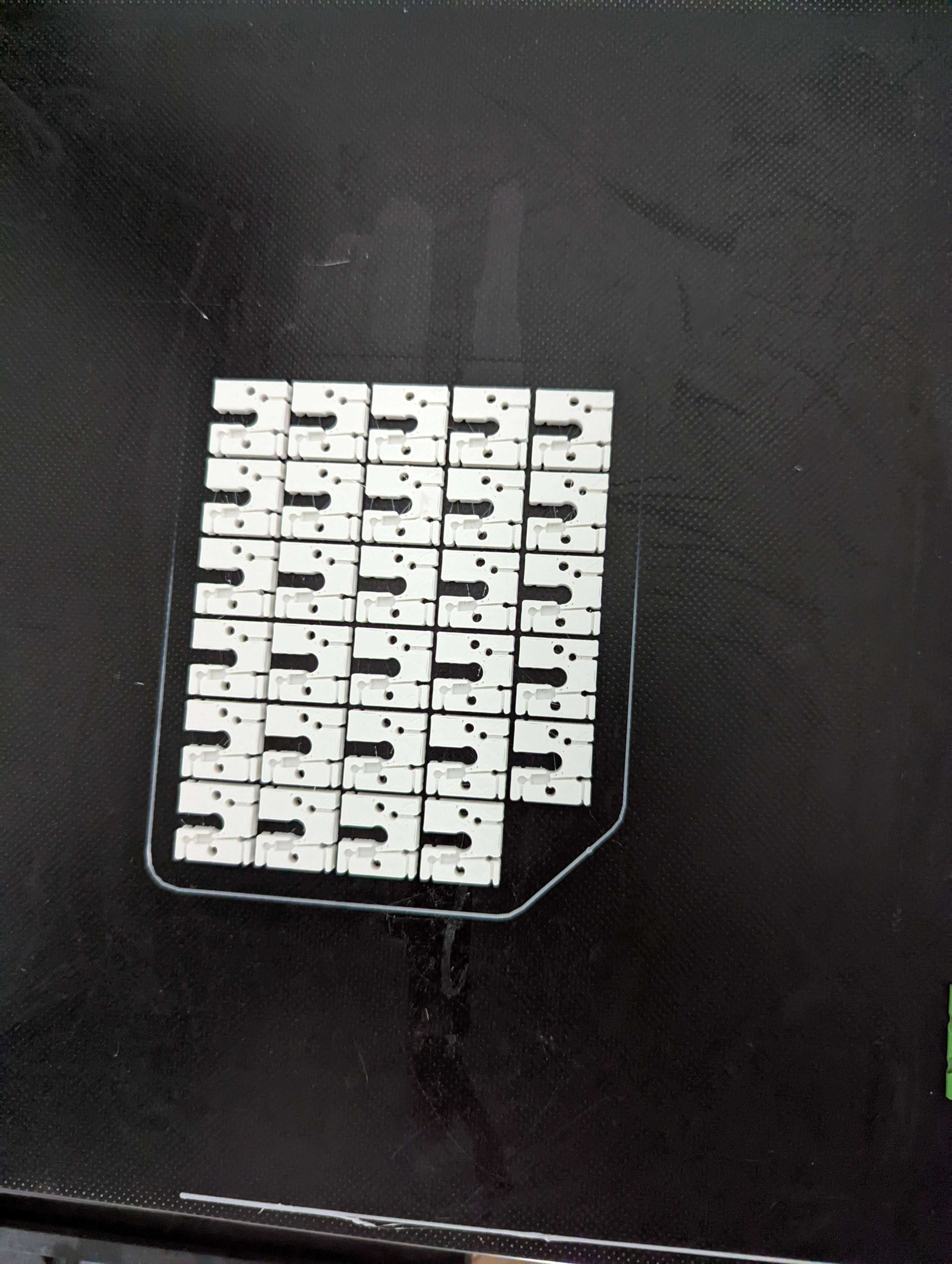
Prepare the hotswap sockets as shown in the instructions on GitHub by folding the diode legs around the socket and creating the loop. This is probably the most time consuming part.
Print the plate and wire the columns
We print the plate for the Soflev2 twice, one time mirrored. Then we can start to wire the matrix. Here I made a mistake, the lip for the switches should be at the bottom for a more secure fit of the swithes in their sockets. I only noticed this after I had completely wire one half and was too lazy to change this. Here I deviated from the description of stringray127: I decided to wire the columns on the same side as the switch (so under the socket if looking at it from the bottom). There is no wire channel (potential improvement?) and one has to take care to wire around the pins of the switch. However, I feel that this way removes any risks of shortening the columns and rows. Turns out there is enough space to do so, perhaps the switches are a bit lopsided but it did not affect their function.
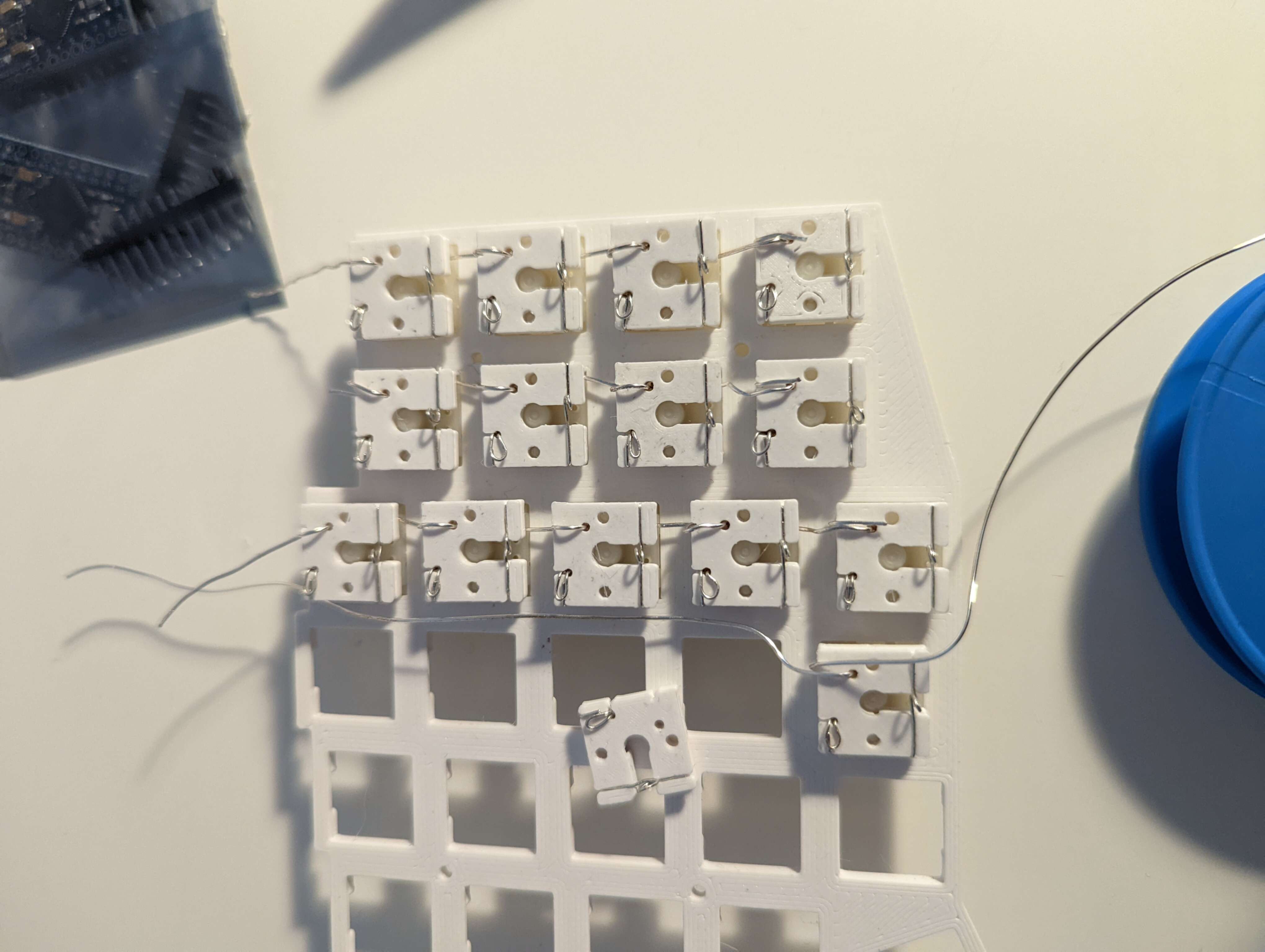
As you can see in the picture the wire loops around the socket through the hole where it makes connection with the switch leg and then goes under the next sockets and loops around from under. In the last socket of each column we do not loop but simply let the end hang out.
Wire the rows
For the rows I just ’snaked’ a wire through the loops of the diode legs. The snaking and the stiffness of the wire ensures a friction fit that is sufficient to make a contact. After I am done with a row I fold the diode loops back into the wire. Mostly works! On the first socket of each row I just made a very tight loop around the diode leg loop. The wire in the other end of the row will be connected to the microcontroller.
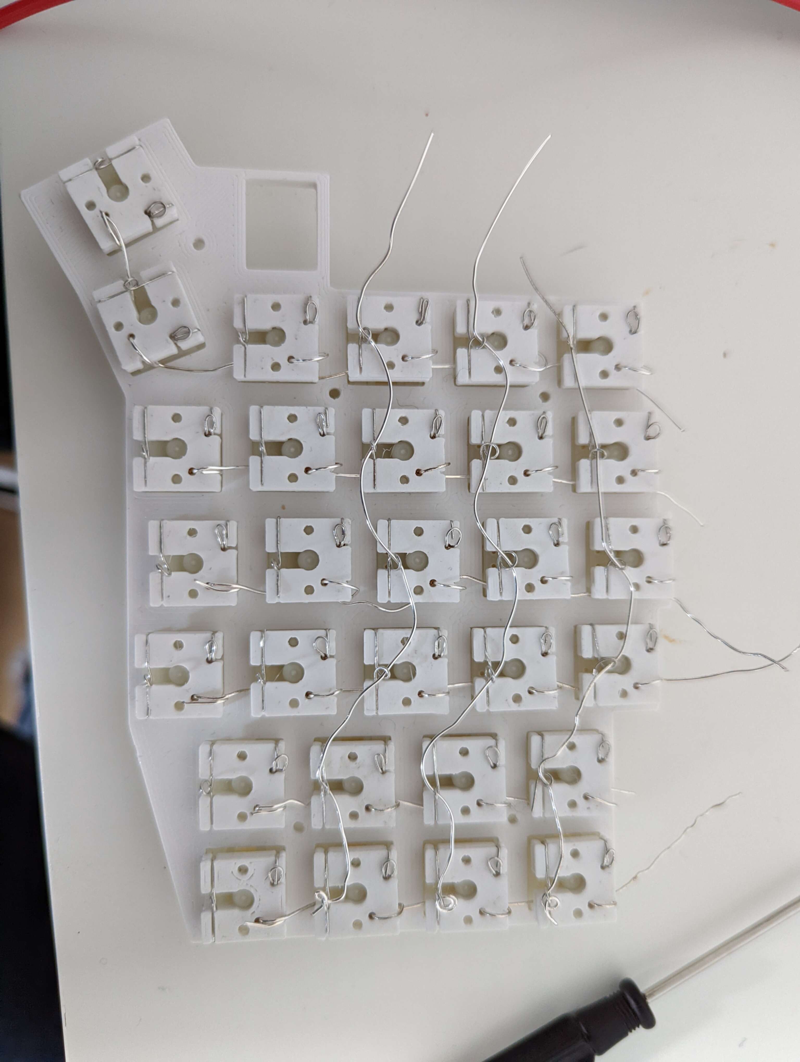
One more note: I my wiring, I wired 7 columns and 6 rows, with the outermost thumb key being in column 7 row 6. This is different than in the sofle PCB, but we have enough pins so why not. On the right side the encoder is also wired to column 7. In the picture above you can see that the outermost thumb key is still wired to the 6th column. I later fixed this.
Crimp cables and connect the microcontroller
Each row is looped around the hotswap socket on one side and left open on the other. We will now use the small gauge wire and crimp female dupont connectors on each end. One end is connected to the bare wire, the other to a pin on the microcontroller. Here you might need to solder on the pin rows onto the microcontroller first if you cannot buy it without That is also very tedious, but I still prefer crimping to soldering.
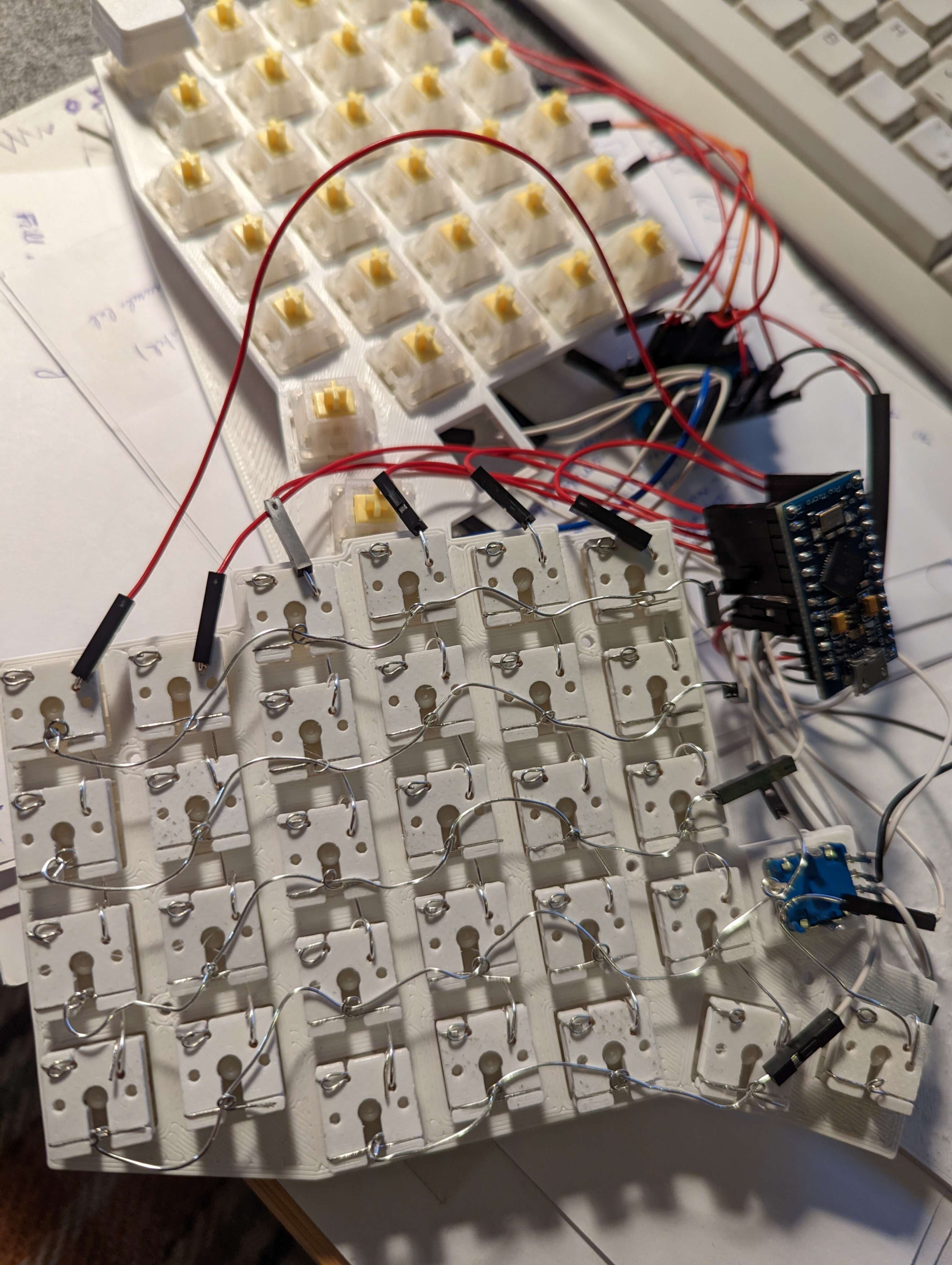
For the encode, I wrapped the row and column wires around the pins of the switch very tightly without bothering to add a diode. This would lead to ghosting if more than 3 keys are held down (including the encoder) but I intend to only press it on its own (currently mapped to mouse button 1) so I did not see a need for a diode. I soldered (yes I know) the small gauge wire directly to the encoder pins and crimped a female dupont on the other end to connect to the microcontroller.
Configuring QMK
After all this wiring, we need to configure and flash the QMK firmware onto the microcontroller. QMK is quite well documented, but I found it was sometimes difficult to find the information as it is in several places. Also QMK is moving to a JSON based configuration but that one is not ready for split keyboards yet creating more confusion. In the end I managed to create a working configuration which has the scanning matrix configured in the same way I wired my matrix. You can find my code on the solderless_sofle branch of my qmk fork. Use this for inspiration but make sure at least change the pin numbers to match your own wiring.
Testing and finishing touches
With a working firmware we are ready to test the keyboard. I used the Test Keyboard function of the QMK configurator. Some keys did not work. Sometimes due to the pins being bent. These I had to remove from the socket, straighten the pins and reinsert into the socket. With this I can confirm that the sockets really allow to hotswap! Some pins just had a bad connection, always due to the row wire being loose. Instead of spending more time trying to get a better fit I just put a blob of solder onto the diode loop to make a stringer connection to the row wire and called it a day. This is one of the reason I am calling this build ’almost’ solderless. However this solder joint is very easy, it does not really matter how much of how little solder you used, there are not traces that can be ripped of, getting any blob of solder to stick to the diode and the wire will make it work. So very easy even with a very cheap soldering iron.
Case building
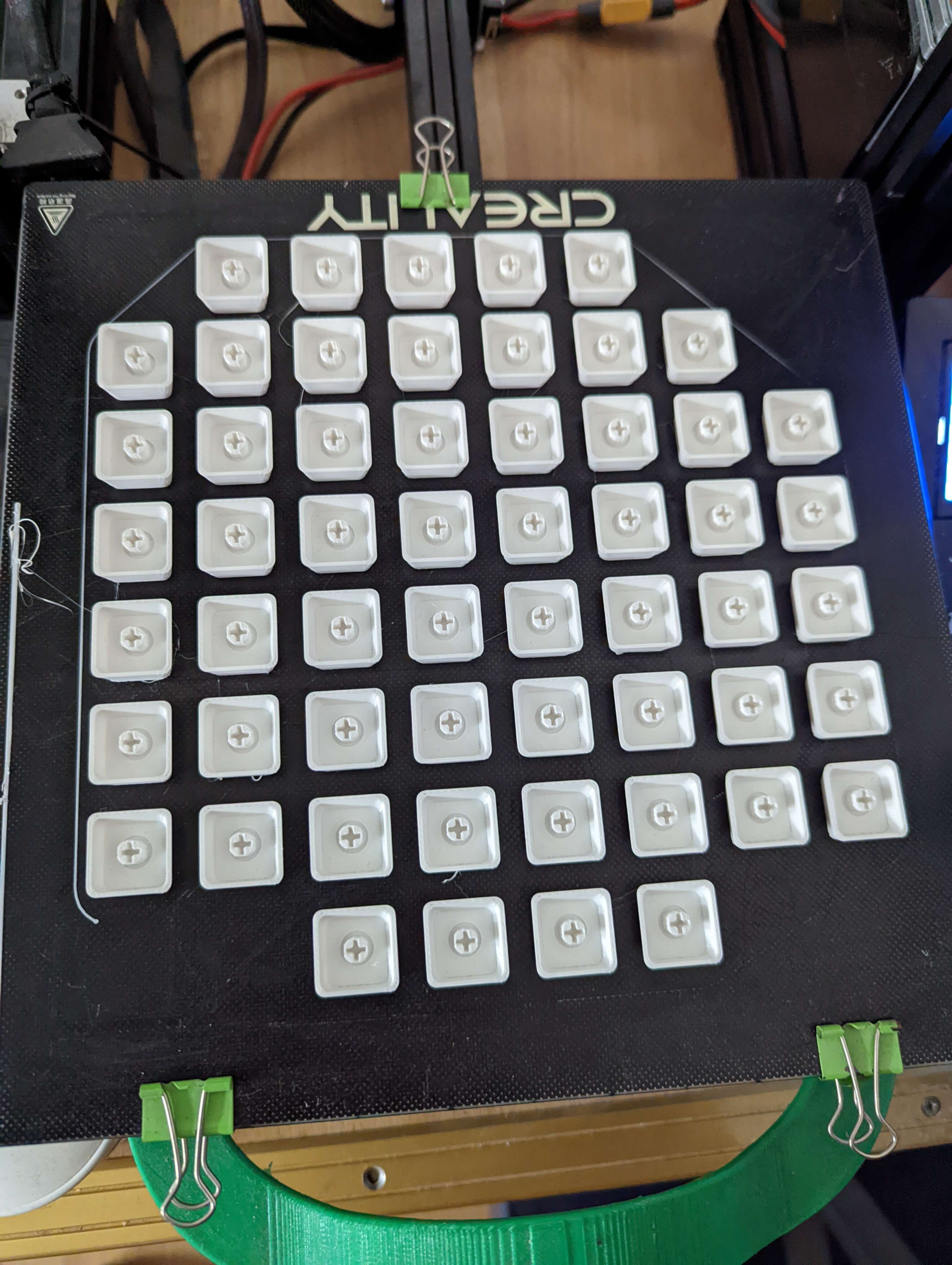
Keycaps
Finally, we need some keycaps. There is am openSCAD library that seems to be doing everything we need, with different profiles and tons of other features. However, I could not manage to get a keycap that would actually fit onto my switches. Maybe my printer is not correctly calibrated or I have not found the right parameters. So instead I printer 58 times this model from thingiverse.
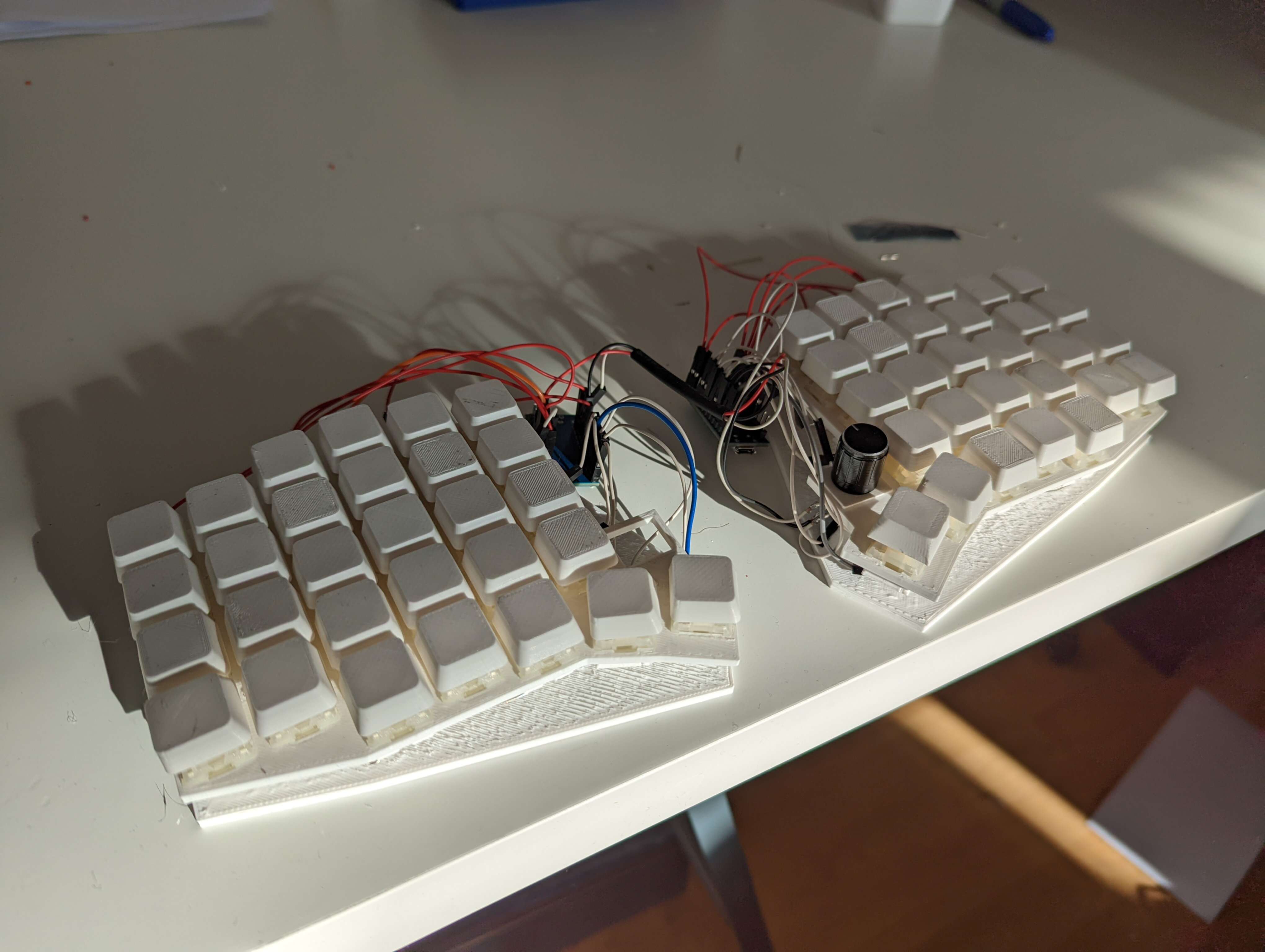
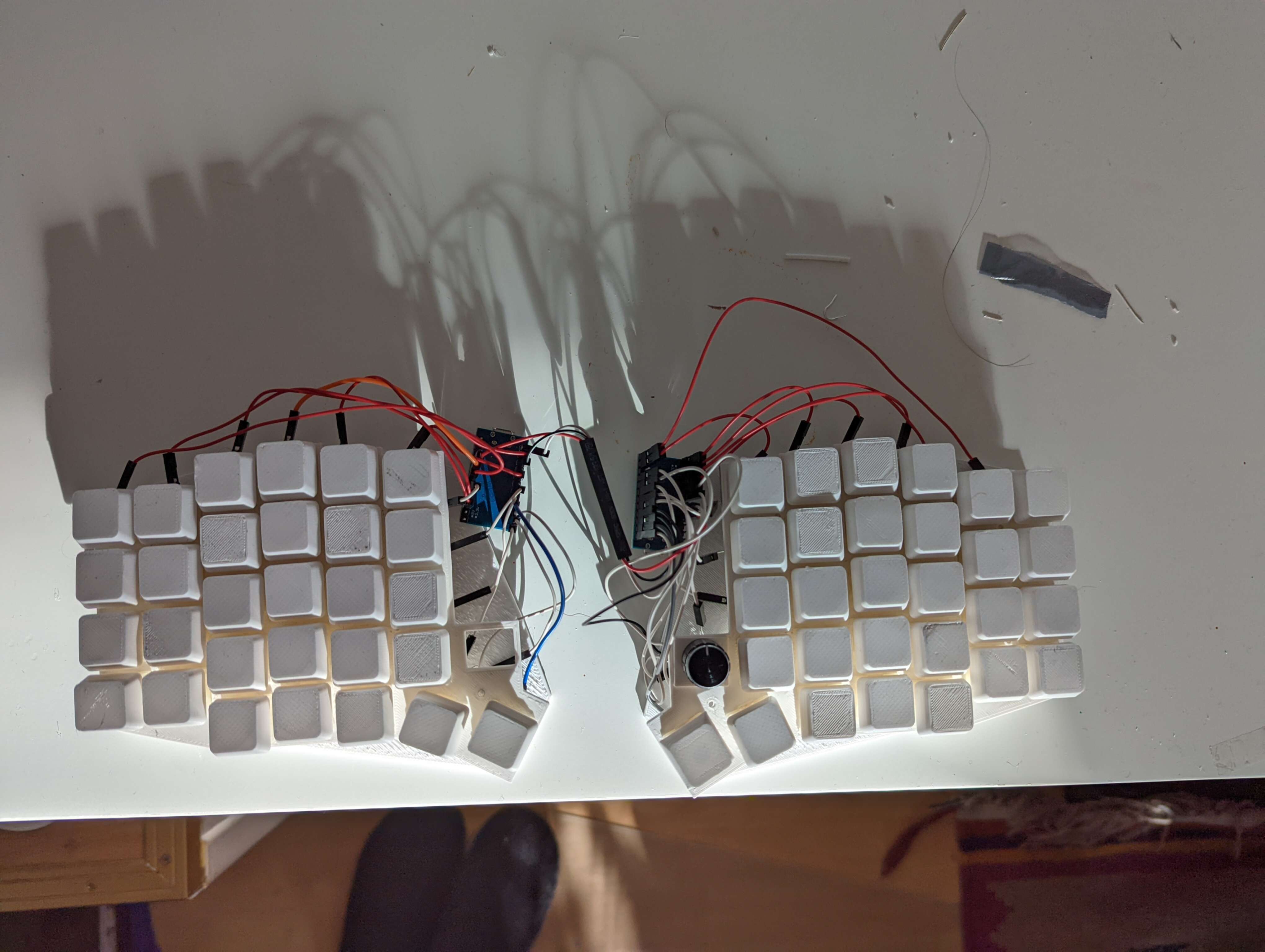
Final result
Let me show you the final results. Is it pretty? No. Does it work? Absolutely! I know that the mechanical keyboard community is very much into aesthetics but my goal here was only to experiment with keyboard without too much costs until I have found a configuration that I feel comfortable with.
Conclusion
It was very fun to mostly use §D printing to build my own keyboard. Since recently having issues with carpal tunnel or RSI on my right hand, I hope that a split keyboard is more ergonomic. I did not use it much yet. I want to also play with tenting (which will need a new case) and of course an appropriate key layout (which is quite the deep rabbit hole and might be covered in a separate post). Then I probably want to try out different keyboard models: Corne, Ferris, Lily58, Dactyl. All of this is possible and I can just re-use the same switches and the sockets since everything is easy to disassemble (apart from the few solder joints). I think this could also be done completely without soldering, if you get the microcontroller with the pin rows already soldered and take more care with the row wiring (perhaps use a different technique altogether). I did perhaps 5 solder joints to fix keys having little contact and of course the 2x24 pins of the microcontroller.