Illuminated Letters
Written by Sebastian Dümcke on
Tags: 3dprinting electronics
This project combines 3D printing and electronics to create large illuminated letters that are slowly fading through different colours. It is based on WS811 LED strips (30 LEDs per meter) and an arduino nano. The LEDs are turned on by a PIR motion sensor, saving energy. You can see the results below:

Design
I designed the letters in OpenSCAD. There are 2 parts to each letter, a base and a diffuser. The base contains holes to hang the letters as well as to thread the cables through to the next letter. I also designed some cable channels and covers to hide the cabling going from one letter to the other. These attach to the bases using a dovetail joint.
One challenge was to get hollow letter bodies. It took me 2 design iterations to end up with this, everything fell in place once I found the OpenSCAD command offset
The letter S has some supports to fix the arduino nano and a hole for the barrel jack. Its diffuser has a cut-out for the PIR motion sensor.
The base is to be printed in a contrasting colour and the diffusers in white. I ran out of blue filament in the middle of the project and use white on the ampersand. As you can see in the picture this changes the light diffusion drastically. You cannot see the LED dots any more and the emitted light is brighter. This is due to the fact that the blue bases absorb some of the light. Incidentally, with the light off, I actually prefer the two-colour letters since white on white on a white wall does not look so appealing. Perhaps if I were to do another version I would spray paint the inside of the letter bases with a reflective colour.
If you happen to have the same initials, you can get the STL files from my GitHub.
Assembly
LEDs
First I cut the LED strips to size. I used 16 LEDs for the letter S, 24 for the ampersand and 18 for the letter N. These are 58 LEDs in total. They draw a maximum current of 60mA/LED at white and full brightness. So that would be 3480 mA or 3.4A in my case. I got a 5V/3A power adapter, since I never run the LEDs at full brightness and also never white, that should be sufficient to power this project. Please make your own calculations.
I then soldered 3 wires to one end of the LED strip, threaded it through the holes in the first and the next letter and soldered then to the beginning of the next strip. Little arrows on the strip indicate the correct direction. The LEDs I got had adhesive on the back so I could attach them along the sides of letter bases.
This part was very fiddly, and I wish I had made the holes for the cabling larger.
Arduino, PIR and power
The arduino is supposed to fit in-between the cylinders in the base of letter S. This works okayish. The barrel connector fits into the hole and screws in place.
I wanted to be able to remove the arduino in order to programm new colour palettes, so I soldered the pins to it and used male-female and male-male cables. In the end I had to solder the power and ground pins directly to the barrel connector so it ended up not being removable after all.
From the power connector I routed power to the LEDs and to the Vin port of the arduino. Then I routed ground to the arduino ground and grounded the PIR sensor and LED strip through the arduino ground. The PIR sensor gets its power from the ardiuno and the signal pin goes to pin D8 on the arduino. The LED signal is attached to pin D5.
Some of this can be seen here: 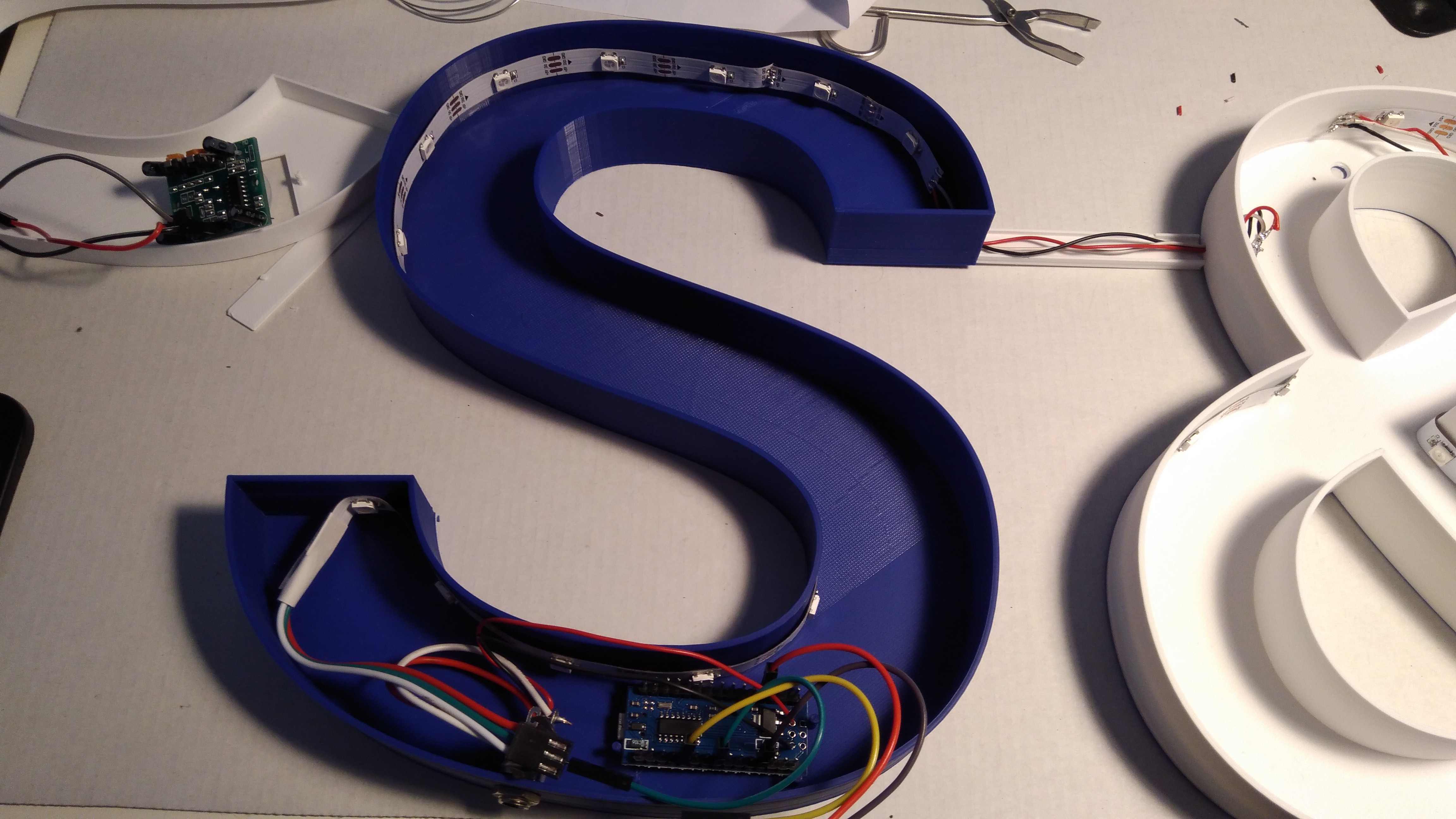
The code is on GitHub. Make sure to adapt the code to the number of LEDs in your project as well as to adapt the pins used to PIR and LED signals.
The code will read the PIR pin, and when it is high it will turn on the LEDs. The LEDs cycle through a colour palette stored in an array. I coded in such as way, that the LEDs resume in the last colour when the PIR signal goes low. The length of time the PIR signal is high can be adjusted on the PIR sensor itself (as well as the angle at which it detects motion). I think I put that on max. This could probably also be controlled in the arduino code with timers, but I decided it is good enough this way.
Bill of Material (BOM)
Here is the BOM for reference: * WS811 LED strips, 30 LEDS per meter, 2 meters * PIR motion sensor (I used a module of type HC-SR501 * Arduino nano * cables (I used 0,16 mm2 in 3 colours black, red, white) * 5V power adapter with wall mart. It should be rated above 3 ampere. I used 5V/3A, and the LEDs are never white and not run at full brightness. Beware to calculate power draw yourself when adapting this project * barrel jack to fit the 5V power adapter * soldering iron and solder
Parting words
This was a fun project and I am happy with the results. As mentioned, there is room for improvement. Having run out of filament creates a weird effect on the ampersand. Due to the design I cannot replace that part without de-soldering the strips which is just too much work. I suggest to spray the body with reflexive paint or use lighter contrasting filament. The holes to thread the cables for the LEDs should be larger, the cable channels are a bit fiddly with their dovetail connections. The diffusers are a good fit, depending on the tolerances of your printer you might want to scale these up or down by a fraction of a percent. The cabling should be much more tidy as it will show when the lights turn on. Again all OpenSCAD design files, the arduino code and the STL files can be found on the project GitHub.