A new keyboard build with only 36 Keys
Written by Sebastian Dümcke on
Tags: keyboards 3dprinting
After having build my solderless SofleV2 keyboard, I discovered, that I could not actually type on it. Even keeping my existing QWERTZ layout I was struggling to hit the right keys. This is due to the fact that this keyboard is “column staggered”, meaning the columns are shifted in relation to a fixed grid while a standard keyboard is “row staggered”, i.e. the rows are shifted relative to each other and compared to a standard grid. That was sufficient to mess up my muscle memory.
At that point I had to retrain myself to use the new keyboard, so I thought, I might as well learn a new ergonomic layout. And then I might also challenge myself and bring down the number of keys. So I wanted a 3x5 keyboard with 3 thumb keys for a total of 36 keys. The actual layout and if/how I learned it to bring the keyboard into daily use will be the topic of a separate blog post. Here I will focus on the design and execution of a split, 36 keys keyboard. As usual it involves 3D printing.
Design
One thing that bothered my in the 1-2 months using the Sofle design was the position of the thumb keys. I want them to be more outwards, i.e. the 3rd, innermost key should not be as tucked in as it is on the Sofle design. The ususal reasoning behind dropping the number of keys is that this ensures that the hands need to move as little as possible to reach all available keys. Missing functionalities and keys are then programmed onto different layers onto the same 36 keys (similar to how the shift keys layers capital letters over the existing alphabetic keys). So with 36 keys, each finger has to reach only 3 keys, with the exception of the index fingers that serve 2 columns/6 keys each.
To generate the plate with the right cutouts for the swithces I used the Ergogen generator with the input below. I tweaked the position of the thumb keys to my preference and also added some splay for the last two columns. The generated layouts can partially be tested by printing them onto paper. If you like the design, you can load the code here into Ergogen and tweak to your convenience.
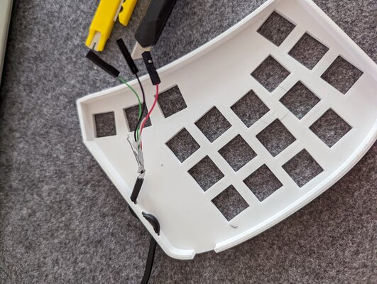
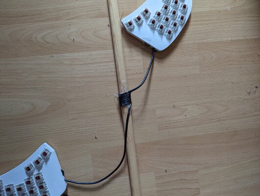
With the ergogen generator providing the positions for the switches/keys, I have then designed a case around this. The case consists of two parts: a switch plate and a bottom plate. The switch plate was designed to have a built in cable relief as I plan to connect the two halves of the board with a cut USB cable. My idea was then that I can freely change the bottom plates in case I want to have e.g. different tenting angles or heights. So far I have not done any such changes.
Lastly, I decided to break out the reset pins to a switch for easier changing/optimizing of layouts by reprogramming the controllers. Previously I had to shorten the pins with a set of tweezers which was awkward and would be difficult in the current design where the controller is inaccessible within the bottom plate.
Execution
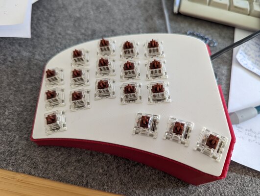
The keyboard is handwired again, using 3D printed hotswap sockets and thin silver coated wire. The wire ends are connected to the microcontrollers (Arduino micro) using cables with JST connectors.
For this, I have re-used the hotswap sockets from the previous Sofle build. For me this is further proof, that these sockets allow for hotswapping switches as well as to be re-usable across builds. I have also re-used the micro-controllers from the previous build (now unusable) and some of the wiring. I did buy new switches (Gateron brown) because I was curious as to how they would feel.
Whilst in the previous build one goal was to avoid soldering, in this build I actually have added solder joints to each of the rows.
I printed a different set of keyscaps, which are not blank but rather include a symbol. For this I used the keycap playground from riskable along with the ’gem’ profile, which was specifically designed for FDM 3D printers. It turned out really well.
Result
First I threaded the cable through the strain relief. I used a broken USB cable where I cut off the connectors.
plate
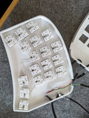
I then created the switch matrix by starting with the columns. As before, I sandwich the column wire between the switch and socket. I feel there is sufficient space to do so and it ensure the wires stay in place. Also this needs no solder at all.
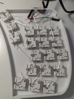
Next I wire the rows. As in the last build I thread the wire through the loops created by the diode legs in the 3D printed sockets (ingenious design) but this time I add some solder as just a friction fit was unreliable. These solder joins turned out quite ugly.
place
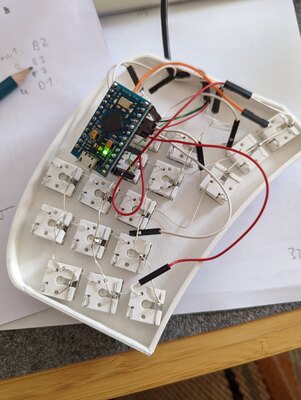
Here you can see one side completely wired up and connected to the micro-controller and the final look with the switches in and the switch plate inside to bottom case
the micro-controller
I had cut off a long length of USB cable to connect the sides (measure twice, cut once, right?). I have really enjoyed having the keyboard halves shoulder-distance apart, which opens the chest while typing, there was still some length of cable beyond this. So I decided to try myself at coiling said cable. The typical approach is to find a round dowel, tightly coil the cable around it, then apply heat (here with a hair blow-dryer) and let is cool down into form. You can see this jig in the image below and then the final result which shows you, that the coiling do not work out so well. However, this showed me that the cable relief works really well and would probably allow transporting the keyboard in the future (something the definitely was not going to happen with the Sofle build).
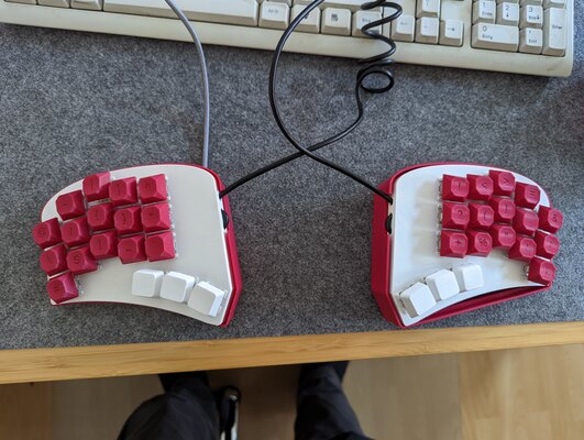
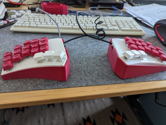
Here is another angle, where you can see the bottom case is used to tent the keyboard (not sure what the degree is, was aiming at 37° tenting). I quite like the use of colors and the contrast between the switch plate and the keycaps and bottom case.
The keycaps do not have the letters printed (as one should know these by heart when touch typing) but rather the symbols that will be part of my symbol layer, which are used much more infrequently and where I thought I might need to visual cues. I will report how that worked out in another post.